OPTICS AND SIGHTS
vision ports, periscopes and weapon sights
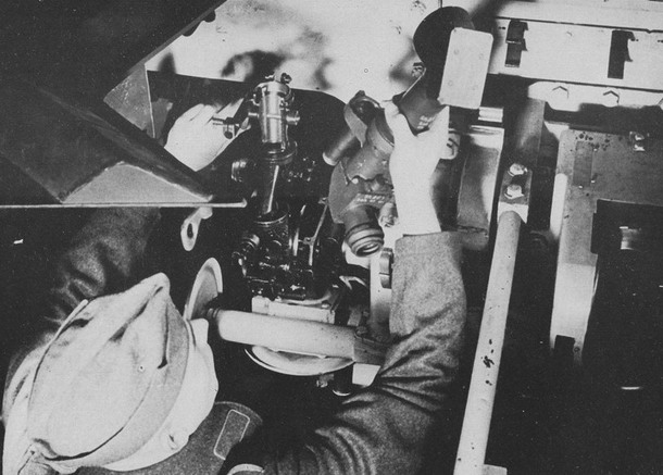
A StuG III assault gun — the gunner is fitting the periscopic Sfl. Z.F. 1 sight, source: Flickr.com with permission of the publishing user, edited
The Driver's Vision Port
Have you seen the 2015 film Battle for Sevastopol? The scene in which a Soviet sniper kills the driver of a German Panzer IV by shooting through the glass block filling his vision port with a rifle? Or the film Saving Private Ryan, in which an American soldier actually pushes the barrel of his Thompson submachine gun directly into the driver's vision port of a German Tiger and shoots the crew? Was it really that easy? Of course not. Both scenes are highly implausible — the American one I would describe as complete nonsense. All the main vision ports of German tanks were designed precisely to prevent such things from happening. Most German tanks had a driver's vision port with a direct view — meaning an actual opening in the armour through which the driver looked straight out. The opening was, however, always filled with a thick block of bulletproof glass (in the Panther Ausf. D, for instance, the glass filling of the driver's port was 9 cm thick!). A spare glass block was also part of the tank's standard equipment, so if the block was damaged the driver could simply replace it with a new one. It was certainly not possible for an enemy infantryman to simply poke a submachine gun barrel through the vision port.
Furthermore, the use of the main vision port was only recommended during road marches. In combat zones where enemy fire was a risk, the driver was supposed to close the main port completely with its external armoured shutter (Fahrersehklappe) and instead use a periscope called the Kampfwagenfahrerfernrohr (KFF) for observation. The main vision port with its glass block was therefore protected from outside in combat mode by an armoured cover of the same thickness as the rest of the front plate, and the driver looked out indirectly through a binocular periscope, whose lenses required only two tiny holes of 15 mm diameter drilled above the main vision port (from outside it looked LIKE THIS and from inside LIKE THIS). The view was limited, but absolutely safe. The scenario from the Russian film was therefore impossible — I'd like to see a sniper hitting a moving target the size of 1.5 cm at, say, 100 metres!
In the Panther tanks, a slightly different periscope was used for the driver's indirect view — one that passed through the hull roof and therefore did not require those two tiny holes in the front plate at all. In Tiger I tanks, the indirect view for the driver was also provided by a periscope, but this time built directly into the hatch cover of the driver's entry hatch (photo HERE). It should be noted that in this case the periscope was not directly above the driver, meaning he could most likely not use it effectively while driving with the main vision port closed and was probably reliant on guidance from the commander. In the later Tiger II and Panther Ausf. G, the direct driver's vision port in the hull front plate was eliminated altogether, leaving the driver with only the safe periscope (photo HERE).
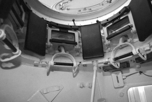
Interior of the commander's cupola of a late-production Panzer IV; the large white levers below the vision ports were used to close the external armoured shutters; the small black levers above the vision ports were for releasing the bulletproof glass block so it could be replaced; the area around the vision ports was padded, source: Flickr.com with permission of the publishing user, edited
The Commander's Cupola
Further fairly large — and therefore vulnerable — vision ports were located in the commander's cupola. The cupola was the highest point of the entire tank and served as a kind of observation post for the commander. To give him a clear picture of the entire battlefield, the cupola was equipped with observation ports around its entire circumference. In early tanks, cupolas typically had direct-view ports filled again with bulletproof glass blocks that could be closed with external armoured shutters (clearly visible in photographs HERE). The risk of the commander being wounded through the vision ports by small-arms fire was therefore also relatively low here. However, a cupola with direct-view ports was necessarily quite tall, and the commander had his head inside its tube. If the cupola took a hit from enemy artillery fire — which did happen — it was typically torn off and thrown aside, often taking the commander's head with it.
Later, more modern cupolas were introduced which had periscopes arranged around their circumference. Such a cupola could be significantly lower, making it a much smaller target, and at the same time the commander's head remained essentially below the turret roof, in considerably greater safety (photo HERE). The individual periscopes were again easily replaceable from inside. The periscope eyepieces, as well as the area around them, were padded to prevent the commander from injuring himself while trying to keep his eyes at the periscopes during movement. All other vision ports in the tank's walls, including narrow slit types, were also practically without exception protected on the inside by a bulletproof glass block (photo HERE). In some late-war tanks, as well as in tank destroyers and self-propelled guns, additional fixed or partially movable periscopes were installed in the turret roof or fighting compartment roof, or there were openings for extending other specialised observation devices (again usually periscopes).
The most important optical device aboard any armoured fighting vehicle was undoubtedly the sight for its main weapon. In German armoured vehicles, two basic types of sight were generally encountered. Tank destroyers and self-propelled guns used telescopic and periscopic sights that were relatively simple in construction compared to tank sights. In tanks, telescopic sights were used with very rare exceptions, their lens (or lenses) looking out through an opening in the front face of the turret (here we somewhat assume that the reader knows the difference between a periscope and a telescope). Let us begin with the more complex but more interesting subject — the sights of tank guns.
The turret of a Panzer IV with the 75 mm gun and the Turmzielfernrohr 5b (TZF 5b) sight, source: wikitanks.com, Creative Commons, edited
Tank Sights
For tank sights the Germans used the somewhat unwieldy term Turmzielfernrohr, abbreviated TZF (literally translated it means something like "turret tube for distant target" :--)). Tank gun sights of the Second World War were not yet stabilised, meaning they did not allow accurate fire on the move — only from a halt. German tank sights were designed for aiming both the gun and the coaxial machine gun, which in most types was mounted alongside the gun in a common mantlet and thus moved with it. The type of sight used in each type of German tank is listed in the following table:
|
Sight |
Magnification |
Field of view |
Gun |
Tank type |
|
TZF 2 |
2.5x |
28° |
MG 13 |
PzKpfw I |
|
TZF 4 |
2.5x |
25° |
2 cm KwK 30 |
PzKpfw II |
|
TZF 5a |
2.5x |
25° |
3.7 cm KwK 36 L/46.5 |
PzKpfw III |
|
TZF 5b |
2.5x |
25° |
7.5 cm KwK 37 L/24 |
PzKpfw IV |
|
TZF 5d |
2.5x |
25° |
5 cm KwK 38 L/42 |
PzKpfw III |
|
TZF 5e |
2.5x |
25° |
5 cm KwK 39 L/60 |
PzKpfw III |
|
TZF 5f |
2.5x |
25° |
7.5 cm KwK 40 L/43(48) |
PzKpfw IV |
|
TZF 9b |
2.5x |
25° |
8.8 cm KwK 36 L/56 |
Tiger |
|
TZF 9c |
2.5x/5x |
28°/14° |
8.8 cm KwK 36 L/56 |
Tiger |
|
TZF 9d |
3x/6x |
26°/13° |
8.8 cm KwK 43 L/71 |
Königstiger |
|
TZF 12 |
2.5x |
28° |
7.5 cm KwK 42 L/70 |
Panther Ausf. D |
|
TZF 12a |
2.5x/5x |
28°/14° |
7.5 cm KwK 42 L/70 |
Panther Ausf. A/G |
A tank sight was by no means a small device. To get an idea, we can look more closely at the Turmzielfernrohr 5b (TZF 5b), used in the early-version Panzer IV tanks armed with the short-barrelled KwK 37 L/24 75 mm gun. The TZF 5b was monocular — meaning it was designed for one eye and therefore had only a single tube. This device measured approximately 81 cm in length and weighed more than 11 kg (and the TZF 5b was certainly not a giant among sights). Every tank sight had to be capable of moving together with the gun. In the horizontal plane this was no problem, since both the weapon and the sight traversed laterally together with the rotation of the entire tank turret. Vertical movement was somewhat more complicated. The sight had to be able to follow the gun barrel's movement up and down, while its eyepiece had to remain in the same position — at the gunner's eye. The only solution was to fit the sight's tube with a joint that allowed it to bend.
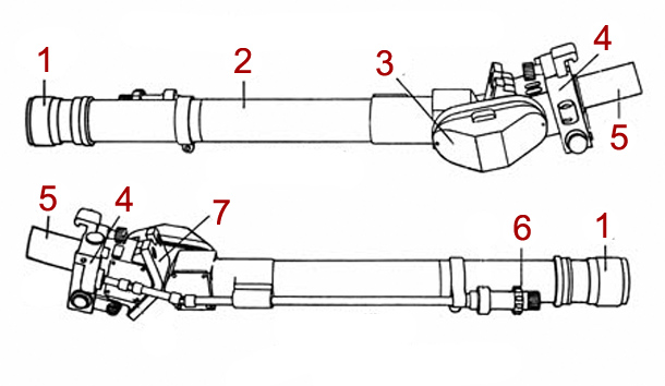
Diagram of the TZF 5b sight from the Panzer IV, published in an American intelligence bulletin in September 1942. 1: gunner's eyepiece, 2: tube fixed permanently to the turret roof, 3: joint connecting the two tubes, 4: housing with movable glass reticle plates, 5: movable tube with the outer lens, 6: selector for setting the target range, 7: armoured plate protecting the gunner against a direct hit on the outer lens, source: public domain, edited
More precisely, it was not one tube with a joint but two separate tubes connected to each other by a joint. The longer tube was attached to the turret roof and did not therefore move with the gun in the vertical plane. At one end of this tube was the eyepiece through which the gunner looked (the eyepiece could be focused to suit the individual gunner's eye). The shorter front tube was connected to the external gun mantlet and therefore moved up and down together with the gun. Both tubes were linked by the already-mentioned joint which made this movement possible. The joint took the form of a connecting link attached to the side. The image from the outer lens was rotated 90° to the left inside the shorter tube by means of an optical prism and directed into the connecting link, where it was rotated 90° to the right to continue in its original direction, then 90° to the right again to enter the second longer tube, and there one final time 90° to the left toward the gunner's eye. If the sight was binocular (for both eyes), it naturally had two tubes placed side by side, each carrying the image to one of the gunner's eyes. The rear end of the shorter tube was fitted with a 10 mm armoured plate designed to prevent injury to the gunner should the lens in the gun mantlet take a direct hit.
Inside the shorter tube was a housing containing two sliding glass plates. The first plate was rectangular and bore the reticle — the aiming pattern used to lay the gun on target. On the second circular plate was a scale for setting the target range. Establishing and setting the target range was one of the gunner's key tasks, particularly after the introduction of effective long-barrelled guns with great range. Getting the range right was half the battle.
Determining Range
The fundamental method for determining target range was the so-called mil method. One artillery mil is an imaginary arc of a circle subtending 0.05625°. This arc has the unique property that at a distance of 1,000 metres from the apex it is exactly 1 metre wide. If such a mil is marked in some way in the sight, the gunner can compare it with the size of the observed target, and if he knows the target's dimensions he can calculate its range.
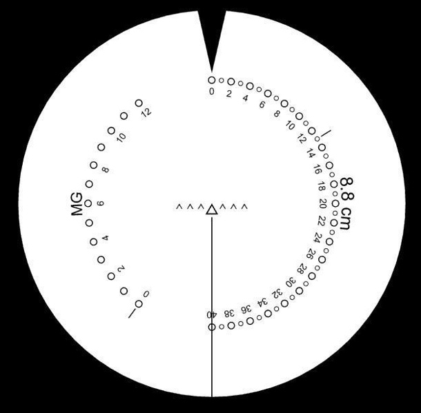
The reticle of the TZF 9b sight of the Tiger heavy tank, with the range indicator set to zero, source: Flickr.com with permission of the publishing user, edited
German tank sights had a reticle consisting of seven triangles placed side by side. The distance between the upper vertices of two adjacent triangles corresponded to 4 mils. This means that if the gunner was looking at a target 1,000 metres away and 4 metres wide, the target would fill exactly the space between the apices of two adjacent triangles. Every tank gunner had to know by heart the dimensions of the main types of enemy tanks, and when he spotted them in his sight he could compare them relatively easily against the reticle and calculate or at least estimate the target's range.
The formula for calculating range was: target width in metres multiplied by 1,000, divided by the number of mils the target occupied in the sight. So for example, if the gunner spotted the side silhouette of a T-34, which he knew was approximately 6 metres long, and this silhouette occupied 8 mils in the sight (i.e. two gaps between triangle apices), he calculated: 6 × 1,000 / 8 = 750 metres. For a clearer understanding, you may prefer to look at the diagram HERE. However, the raw range figure alone was not sufficient to correctly set the sight. If the gunner simply set the sight to 750 metres, the shell would land at the base of the target. To hit the target in its centre, he also had to account for its height. A simple procedure existed for this. The gunner had to estimate the target's height in mils (by comparing it with the central aiming triangle, whose height was 4 mils). Let us say he estimated the target's height at approximately 3 mils (as in the diagram HERE). He then simply took half of this estimated height (i.e. 1.5), multiplied it by 100 metres (1.5 × 100 m = 150 m) and added this value to the previously determined target range — and voilà, we have the number to set in the sight: 750 + 150 = 900 metres. If this all sounds complicated, bear in mind that in actual combat the gunner of course did not carry out such precise calculations. He relied primarily on experience and trained estimation. Moreover, hitting a target did not require everything to be calculated to the nearest metre or even to the nearest ten metres. The margin was in the hundreds of metres, as explained for example in the Tiger crew manual HERE.
Setting the Gun Elevation
A shell fired from a gun (as from any other weapon) travels along a so-called ballistic curve. Beyond a certain point in its trajectory it simply begins to drop and eventually hits the ground. When firing at longer ranges it is therefore necessary to account for this drop, and the gunner cannot aim directly at the target but must aim slightly above it. This is precisely where the second glass plate — the one bearing the range scale — came in. Let us work through the process step by step. Our tank is stationary, the gun barrel is horizontal, the sight is set to zero range, and the gunner has just spotted an enemy tank in his field of view. The gunner traverses the turret to centre the target in the sight, then calculates or estimates the target's range (as described above). He determines that the target is approximately 750 metres away and its height is 3 mils. On his left-hand side, mounted directly on the sight tube, is a wheel for entering the required range into the sight.
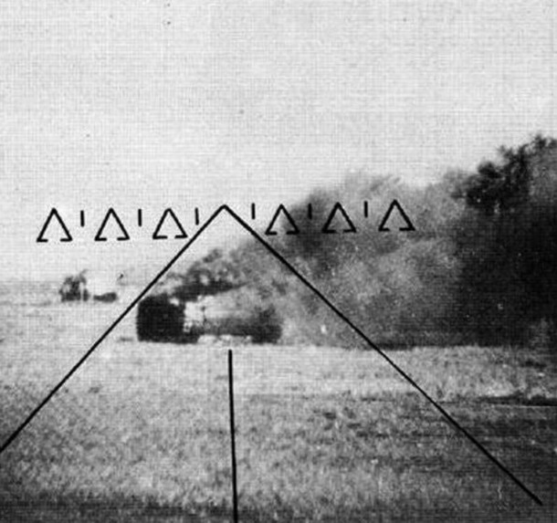
View of a burning T-34 through the Sfl. Z.F. 1a sight of a Ferdinand tank destroyer, Kursk salient, summer 1943, source: Flickr.com with permission of the publishing user, edited
The gunner then turns the wheel to increase the set range from zero up to 900 metres. Turning the wheel sets both glass plates in the sight in motion. The circular plate with the scale around its rim begins to rotate about its axis. The gunner continues until the indicator at the top of the field of view shows the required value of 900 metres. Turning the wheel, however, also moves the second glass plate — the one carrying the reticle. As the range is increased, this plate slides downward, so the seven triangles forming the reticle appear to drift down and away from the observed target. Once the gunner has set 900 metres, he sees the apex of the central triangle deep below the target. What does he do? Correct — he must begin elevating the gun barrel upward to bring the triangle back onto the target. The sight is coupled to the gun, so the angle of barrel elevation corresponds precisely to the ballistic curve for firing at the set range of 900 metres. Perhaps the simplest way to understand the full procedure is to look at the diagrams HERE.
Some readers may notice that after elevating the gun the gunner no longer sees the target in the centre of his field of view but somewhere in its lower portion. That is exactly right. Recall that the shorter front tube of the sight is connected through the gun mantlet to the barrel, so if the barrel is pointing above the target, the sight's lens is also pointing above the target. But could it happen that the gunner elevates the gun so high that the target disappears off the bottom of the field of view and cannot be seen at all? Theoretically yes — but in practice no. The sight's field of view generally corresponded to the range of the gun's vertical movement (the elevation arc). For example, the Panther's TZF 12 sight had a field of view of 28°, and the Panther's gun elevation range was -8° to +20°, a total of 28°. The Tiger II's TZF 9b/1 sight had a field of view of 25°, while the Tiger II's gun elevation range was -8° to +15°, a total of 23°. In short, even at maximum positive elevation the target (and the reticle image) could not escape beyond the sight's field of view.
In connection with the vertical movement of the sight's lens, one further point is worth mentioning. Most German tanks of the Second World War had a gun mantlet wide enough to also accommodate the sight. The front movable tube of the sight was therefore connected to the mantlet and moved up and down together with it. In the mantlet it was therefore possible to drill only a very small round hole for the lens (the lens remained in the same position relative to the mantlet — they moved together). However, some tanks had a much smaller gun mantlet and the aperture for the sight lay outside it. This was the case with the Panzer IV and the Königstiger, for example. In these tanks the hole for the lens was drilled directly in the front face of the turret and the lens moved up and down relative to this face. In such cases a round hole was insufficient — an oval opening was needed that allowed the lens a clear view throughout its vertical travel (compare the photographs HERE).
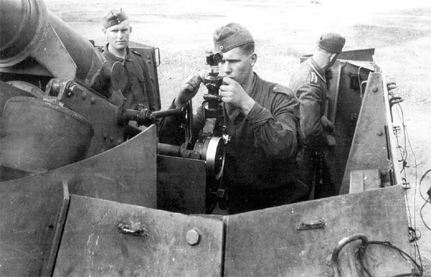
The Hummel self-propelled gun and its gunner at the Rundblickfernrohr 32 sight, source: Flickr.com with permission of the publishing user, edited
Coincidence Rangefinder
As already noted, correctly determining target range was crucial for accurate fire — and this applied not only to tank gunnery. The crews of anti-tank or anti-aircraft guns therefore often had a specialised instrument to assist with range-finding. This was another interesting optical device known as a coincidence rangefinder. This type of rangefinder consisted of two adjustable optical prisms mounted at the ends of a long tube. The observer looked into an eyepiece located at the centre of the tube, where the images from both prisms met. If the observer saw a double image of the target, it meant the two prisms' lines of sight were not converging at the correct point. The observer therefore had to rotate the prisms until he obtained a single unified image of the target. At that moment both prisms were precisely aimed at the target and, using trigonometry, the range to the target could be calculated relatively easily.
The coincidence rangefinder had one significant drawback, however. For it to be reasonably accurate, its optical prisms had to be positioned a considerable distance apart from each other — accuracy increased with the separation of the two prisms. A typical rangefinder as used with anti-aircraft guns therefore looked LIKE THIS; on battleships, rangefinders were installed whose tubes measured more than 10 metres. This characteristic rather limited the potential uses of coincidence rangefinders in tanks. Nevertheless, the Germans did plan exactly such an application. The planned Panther Ausf. F was to have a rangefinder mounted directly inside the turret, with its lenses looking out through apertures in bulges on either side of the turret.
Zielfernrohr 3x8
Let us now briefly look at the sights used in German tank destroyers and self-propelled guns. The early tank destroyers Marder I, Marder II and Marder III, armed with 76.2 mm and 75 mm guns, were fitted with the Z.F. 3x8 sight (Z.F. = Zielfernrohr), which was also used on the towed versions of those guns. This was a simple telescopic sight with 3× magnification and an 8° field of view. The older version of the Z.F. 3x8 had a reticle consisting of only three stadia marks. In the newer version the gunner saw seven open triangles, with the distance between the apices of two adjacent triangles corresponding to 4 mils, further subdivided at the halfway point by an auxiliary line. Compared to tank sights, the Z.F. 3x8 was very simply constructed — it had virtually no moving parts: no joint, no sliding reticle plate, no range indicator.
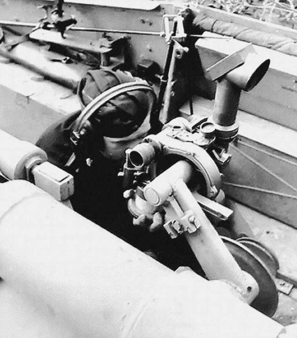
The Nashorn tank destroyer with its periscopic Sfl. Z.F. 1 sight, source: Flickr.com with permission of the publishing user, edited
Range calculation and estimation were performed in exactly the same way as with a tank sight — by comparing an object of known size against the reticle. Once the gunner had calculated or estimated the target's range, he set it not in the sight itself but using a scale on the sight's mounting bracket. This tilted the entire sight downward by a corresponding amount, causing the target to "escape" from the centre of the field of view. To bring the target back to the centre of the reticle, the gunner had to elevate the gun barrel, and the sight rose upward together with the gun. When the target returned to the correct position in the sight as the barrel was raised, the barrel was at the angle corresponding to the set range. For horizontal aiming, even turretless tank destroyers could make use of a limited traverse of the gun (in the Marder II with the 76.2 mm gun, for example, this was 25° to each side); if that was insufficient, the driver had to rotate the entire vehicle.
Rundblickfernrohr
True self-propelled guns (German: Selbstfahrlafette) performed essentially the same role as conventional artillery and therefore used the same or similar sights. These were sights designed for indirect fire — fire in which the gunner does not see his target at all. Such sights therefore did not need to incorporate any range-calculation capability of their own. Target range and position were determined by other means, the detailed description of which I do not feel sufficiently qualified to provide here. In any event, in an era without GPS and in areas without triangulation networks, this was fairly complex work involving a topographic map, a compass and a theodolite, requiring the most accurate possible determination of one's own firing position, the forward observation post and the position of the target itself. Once the mutual positions of the gun and target had been established (so-called "registration"), gunnery tables told the crew what elevation and propellant charge to use to deliver a chosen type of round to the required range. Meteorological factors also had to be incorporated — particularly wind speed and direction, temperature and humidity. A typical example of the sights used with these self-propelled guns was the periscopic Rblf 32 (Rblf = Rundblickfernrohr).
Selbstfahrlafette Zielfernrohr 1
Later and more advanced tank destroyers (Jagdpanzers), assault guns (Sturmgeschütz), and also so-called Sturmpanzers — in short, vehicles with a fully enclosed armoured fighting compartment — typically used the Sfl. Z.F. 1 sight (or Sfl. Z.F. 1a) (Sfl. Z.F. = Selbstfahrlafette Zielfernrohr), which allowed both direct and indirect fire aiming. The Sfl. Z.F. 1 had the same reticle as the already-mentioned Z.F. 3x8 — seven open triangles with a spacing of 4 mils between them. Magnification on the Sfl. Z.F. 1 was 5× and the field of view was either 8° or 10° (sources disagree). The Sfl. Z.F. 1 was periscopic in design and extended out through an opening in the roof of the fighting compartment. Range setting was again performed via the sight's mounting bracket rather than within the sight itself.
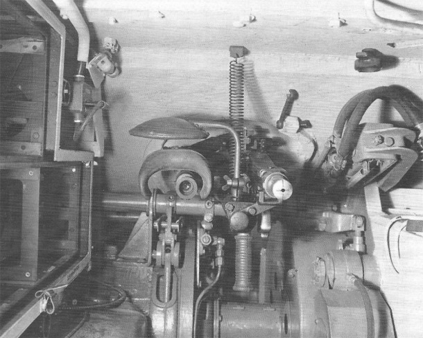
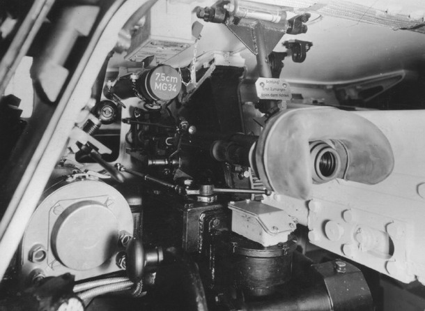
The MG 34 machine gun in the hull of a Panther Ausf. A with the Kugelzielfernrohr 2 (KZF 2) sight; above the sight's eyepiece is a padded head rest for the gunner; hull machine guns in tanks standardly had no butt stock, source: Flickr.com with permission of the publishing user, edited
There were also vehicles fitted with two sights — one for direct fire and one for indirect fire (for example, the early versions of the Nashorn tank destroyer). The gunner thus changed sights depending on how he intended to use the weapon. This arrangement was not particularly popular, however, as it placed greater demands on the gunner and changing sights inevitably caused misalignment of the aiming system. On the later versions of the Nashorn, a single sight was therefore used — the already-mentioned "universal" Sfl. Z.F. 1a.
Kugelzielfernrohr 2
The last sight we will mention was the Kugelzielfernrohr 2 (abbreviated KZF 2), which was used for aiming the machine guns mounted in ball mounts in the hull of tanks. The KZF 2 had 1.8× magnification, an 18° field of view and a very simple reticle consisting of a single central triangle and three auxiliary lines converging on it from the sides and from below.

ARTICLE
CONTENTS:
Reproducing text from the Panzernet website without the written consent of the operator is prohibited.