10,5 cm LG auf VK 3.01
self-propelled gun on an ammunition carrier chassis
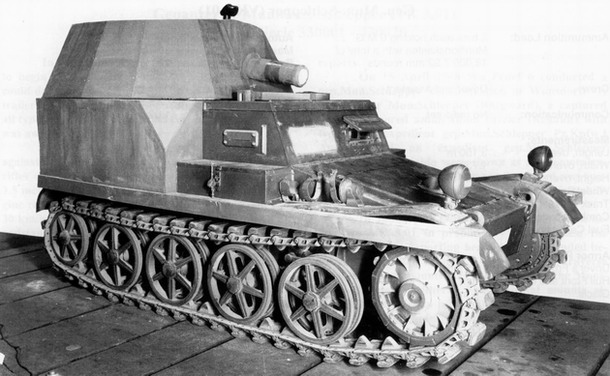
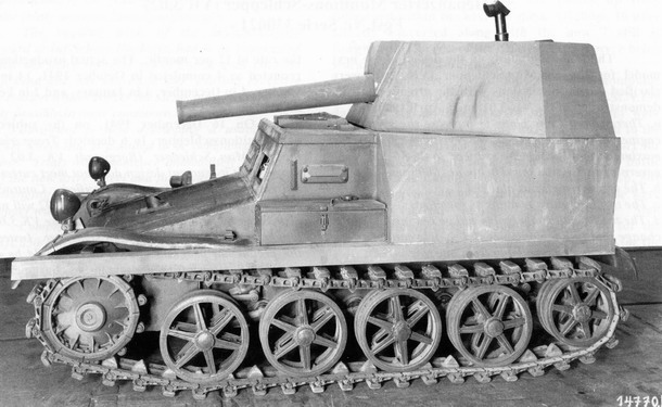
technology demonstrator of the self-propelled gun on the VK 3.01 chassis, with a wooden mock-up of both the fighting compartment and the weapon — note the short barrel and the blanked-off right vision port, source: Flickr.com with the permission of the publishing user, modified
Origins of the Project
The self-propelled gun described on the following pages would be searched for in vain among the reports of front-line units. It never reached series production, nor even the construction of a prototype that might have undergone live trials in combat. Its development ended at the stage of a bare mock-up, with wooden stand-ins for both the fighting compartment and the armament — we might use the slightly grander term technology demonstrator. The intended foundation of this self-propelled gun was to be the ammunition carrier VK 3.01, developed between 1937 and 1940 by Borgward. The VK 3.01 was designed as a fully tracked vehicle capable of carrying up to 1,000 kg of cargo. Its purpose was to deliver ammunition to the infantry directly into the front line, where it would be exposed to enemy fire — which is why it had to be armoured, with frontal protection sufficient to withstand rifle and machine gun fire of 7.92 mm calibre.
Borgward delivered a total of 20 evaluation examples of the VK 3.01 to the army. Production of this version then ceased, since testing had led to a range of proposed improvements that ultimately resulted in an entirely new variant designated VK 3.02. Nineteen of the twenty VK 3.01s built were subsequently transferred to the infantry school (Infanterie Schule) at Döberitz, where they underwent further thorough trials at the turn of 1942–43. Later still, in June 1943, these vehicles travelled as part of the special ammunition company Gepanzerter Munitions-Schlepper Kompanie 801 alongside the 1st Infantry Division to the northern sector of the Eastern Front, where they saw active combat. What concerns us here, however, is the fate of the one vehicle from the twenty that did not go to the front and remained in Germany. Its production number was B330016, and it was this particular example that Rheinmetall used as the basis for designing a light self-propelled gun.
Almost no details are known about the background of this project's inception. From the historical context, however, it can be inferred that the intended vehicle was to be capable of air transport. It was to serve not only airborne units but any infantry formation for which delivering such a weapon by air made sense — for instance, units operating far from main supply routes, units cut off from the rest of their own forces, or units in urgent need of a means of artillery support.
Vehicle Description
The running gear that the proposed self-propelled gun inherited from the VK 3.01 ammunition carrier consisted of four road wheels on each side. These were spoked wheels with a solid rubber tyre around their circumference. Each wheel was mounted on its own swing arm and sprung by a torsion bar. At the very rear was an idler wheel, similar in appearance to the road wheels but of smaller diameter. Both the road wheels and the idler were double units — each formed by a pair of discs — with the track guide horn passing through the gap between them. The drive sprocket was at the front. Tracks were 200 mm wide and fitted with rubber pads for smoother running on hard surfaces. The vehicle was powered by a Borgward 6M 2.3 RTBV petrol six-cylinder engine with a displacement of 2.247 litres producing a maximum output of 49 horsepower. The engine was located in the centre-rear of the vehicle, with the gearbox at the front of the hull.
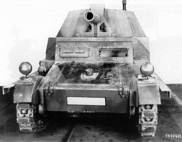
the demonstrator in this photograph has a mock-up gun with a longer barrel and the right vision port is not blanked off; the L-section profiles along the sides of the vehicle most likely indicate its expected final width, source: Flickr.com with the permission of the publishing user, modified
The entire front half of the hull, including the cab of the VK 3.01's original two-man crew, was retained essentially unchanged. The original cargo space in the rear of the vehicle was replaced by a new fighting compartment — or rather its wooden mock-up. The fighting compartment had a fixed lower base, above which sat what was probably a partially rotating mount. Both sections were open at the rear and from above, however, so rather than a "turret" one might more accurately call it a kind of enlarged gun shield. The raised engine cover ran down the centre of the fighting compartment, terminating at the rear in a grilled exhaust vent for hot air. The gun was mounted above the engine, on which more shortly. The engine cover and the weapon above it divided the interior into two halves. To the left of the engine and gun sat the gunner, who also served as vehicle commander. In the right half sat the gun loader.
The range of movement permitted to the gun by its mount is not known. As for vertical elevation, surviving photographs of the technology demonstrator show the barrel both at a slight negative angle and at a positive angle estimated at up to around 25 or 30 degrees. For horizontal traverse, it seems probable that only limited movement was possible — perhaps 10 or 15 degrees to each side. A wider arc of traverse, let alone a full 360 degrees, was out of the question for the simple reason that the seats of both crew members alongside the gun were part of the fixed base and did not follow the gun's rotation. Any significant traverse would therefore have caused the rear of the gun to strike one of the crew members squarely in the head.
The Recoilless Gun
What gun did the designers actually manage to fit onto the slender chassis of an ammunition carrier? In truth, they had very little choice. A conventional gun or howitzer was essentially out of the question — not only would the chassis most likely have been unable to bear such a weight, but the forces generated by firing a weapon of that kind would in all probability have quite literally torn it apart. What was needed was a weapon that, even at a relatively large calibre, would be light and would not impose excessive additional stresses during firing. And that was precisely what the so-called recoilless guns had to offer.
Every firearm produces recoil when fired. In accordance with Newton's third law of motion, this is the reaction equal and opposite to the action performed on the projectile. Simply put: while the projectile moves in one direction, the rest of the weapon tends to move in the opposite direction. In a pistol or rifle the recoil force is small enough for the shooter to control with their hands, but in artillery weapons it represents an enormous amount of energy. To prevent this energy from stressing the entire structure of the gun, the barrel is not rigidly attached to the carriage but connected through a movable recoil mechanism. This allows the barrel, driven back by recoil after firing, to slide rearward — the so-called recoil stroke. The recoil mechanism controls this movement, safely arrests the barrel's travel and then returns it to its original position. In doing so it absorbs the majority of the recoil energy, acting in effect as a large shock absorber between the barrel and the carriage. Even so, a significant residual force always remains that the carriage itself — in the case of a self-propelled gun, the tracked chassis — must absorb.
again the version with the longer gun barrel, source: Flickr.com with the permission of the publishing user, modified
The chamber, barrel, recoil mechanism and carriage all have to be robustly built, which is why powerful guns are also very heavy. There are, however, military units that need artillery support yet simply cannot bring heavy weapons with them — in the German Wehrmacht this was typically true of airborne troops and mountain infantry. It was for exactly these kinds of units that the so-called recoilless guns were developed. In a conventional gun the barrel is open only at one end — the muzzle — while the opposite end is closed by the breech. The energy of the propellant charge therefore pushes against the shell in one direction, driving it out of the barrel, and pushes against the breech in the other, loading the entire gun structure. In a recoilless gun the chamber is open in one way or another, so the barrel effectively has openings at both ends, and a portion — ideally half — of the propellant energy escapes rearward through the back. When everything works as intended, comparably large forces act against each other in opposite directions at the right moment, cancelling one another out, so that the barrel of a recoilless gun scarcely moves during firing — no recoil occurs.
There is no need for a massive breech, no recoil mechanism, and indeed no thick-walled barrel or heavy carriage. As a result, a recoilless gun is significantly lighter than a conventional gun of the same calibre. As usual, however, there is a trade-off. Because a substantial portion of the propellant pressure is vented rearward from the chamber rather than being used to propel the shell forward, muzzle velocity is inevitably lower and range correspondingly reduced. A recoilless gun using the same propellant charge as a conventional gun will therefore have considerably shorter range.
LG 40 or LG 42?
Let us return to the proposed self-propelled gun on the VK 3.01 chassis. As will by now be clear, a recoilless gun of 105 mm calibre was selected as its armament. The sources are not entirely clear, however, on which specific type was intended — whether the 10.5 cm LG 40 by Krupp or the 10.5 cm LG 42 by Rheinmetall (LG = Leichtgeschütz = light gun). The appearance of the wooden mock-up on the technology demonstrator would suggest the LG 42, with its horizontally sliding breech, but the majority of sources point instead to the LG 40. In the end it would most likely have been a modified version of one of them, and according to some authors the intended weapon even acquired its own designation: 10.5 cm LG 5.240. In any case, the gun had to be positioned well to the rear of the fighting compartment, so that the gases and debris ejecting from the rear nozzle would not endanger the crew. For the loader, however, such a rearward position would have been a genuine nightmare — not only would he have had to reach back with a 15-kilogram shell, but the aforementioned sliding breech block would have been in his way, opening as it did by sliding sideways precisely towards his side — that is, to the right.
The LG 42 — and the same applied to the LG 40 — used separate-loading ammunition: the shell and the propellant cartridge were loaded independently. Both the LG 42 and the LG 40 fired the same shells as the conventional leFH 18 field howitzer, but used entirely different cartridge cases. The cartridge case for the recoilless gun was more than twice the size of that for the leFH 18, yet even so the maximum range of the LG 42 fell short of the leFH 18's range by around a quarter — a consequence of what was said above about recoilless guns. While the LG 42 could send its 15 kg shell to a maximum distance of 7,950 metres, the leFH 18 could reach 10,695 metres.
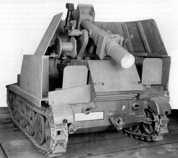
the recoilless LG 42 gun was mounted well to the rear of the fighting compartment so that the nozzle behind the breech would not endanger the crew, source: Flickr.com with the permission of the publishing user, modified
The cartridge case for the recoilless gun had another distinctive feature. Almost its entire base consisted of a plastic disc that the explosion of the propellant charge shattered, opening the path for the pressure to escape rearward. For this reason the cartridge case could not have its primer located in the base — as is conventional in most cartridges — but instead had it positioned on the side. This in turn required precise insertion of the cartridge into the weapon, specifically oriented so that the primer was aligned with the firing mechanism. The gun's barrel was rifled to impart spin to the shell. The rear nozzle also had rifling grooves, running in the opposite direction to those in the barrel. Their purpose was straightforward: to counter the torque generated in the barrel. While the shell, passing through the barrel, twisted the entire gun structure in one direction, the gases escaping through the rear nozzle twisted it back in the other. The net stress on the weapon was therefore lower than it would have been with a plain, un-rifled nozzle.
Open Questions
As for the official designation of the proposed self-propelled gun, it is sometimes found as Rückstossfrei Kanone (Sfl.) auf VK 3.01, though the more common form is 10.5 cm LG auf Gepanzerter Munitionsschlepper VK 3.01. The surviving photographs of the technology demonstrator reveal several interesting details while also raising a number of questions that will in all likelihood never be answered. The first of these details is the width of the fighting compartment's base. Its wooden mock-up protrudes noticeably beyond the original track mudguards on both sides. Retaining the original width would evidently have provided insufficient room for the gun crew. The self-propelled gun would therefore most probably have required wider mudguards over the tracks, something demonstrated on the mock-up by long L-section profiles extending along the original mudguards (photograph HERE). Alternatively, this could be interpreted as the designers simulating the width of the wider VK 3.02 chassis — suggesting that any future production was already expected to use the newer, broader chassis.
In some photographs the vision port in the cab in front of the co-driver's position is blanked off. This suggests the designers were planning to eliminate this crew member, do away with his station and most likely use the space for ammunition stowage, as the cramped interior offered no other suitable place for rounds. The mock-up photographs also reveal that the entry hatches on the roof of the original driver's and co-driver's cab were eliminated, and a folding travel support for the gun barrel appeared on the roof in their place. This immediately raises the question of how the driver was actually supposed to get in and out, given that his own hatch had been removed. From the photographs it does not appear that any hatch into the open fighting compartment behind him was provided.
The biggest puzzle of all, however, is the two different barrel lengths clearly visible in the demonstrator photographs. Two different designs of the rear nozzle on the gun mock-up can also be made out. It simply appears as though the designers used two different gun mock-ups — one with a shorter barrel and a cylindrical nozzle, and another with a longer barrel and a conical nozzle (see photographs HERE and HERE). But what was the reason for this? Were genuine alternative modifications of the LG 42 actually being considered, or was it simply an insignificant simplification in the construction of the wooden mock-up — or even a mistake that was later corrected? None of the available sources addresses this detail. What we do know for certain is that the recoilless gun project on the VK 3.01 chassis progressed no further and was cancelled.
ARTICLE
CONTENTS:
Reproducing text from the Panzernet website without the written consent of the operator is prohibited.